Case study
The 5-Axis Motion Machine
This machine is a significant breakthrough for our client, as it opens up new possibilities in X-ray and CT imaging for a wide range of objects.
Requirements for the machine
The system should be a 5-axis motion machine, to be able to handle samples weighing up to 300 kg and measuring 2.5 meters in height. The vertical motion range should be 2.5 meters, while the horizontal motion range should be 2.4 meters. The system should have a motion resolution of minimally 0.2 micrometers. The maximum angular parasitic motion has to be below 5 microradians. The angular error for the end effector should be below 17 microradians. The sphere of confusion should be within 500 nanometers.

Solution: the motion machine
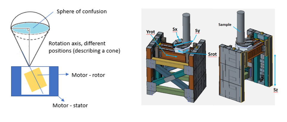
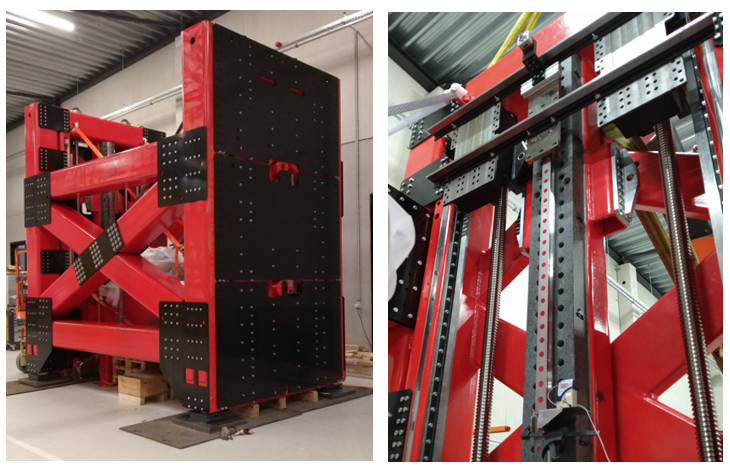
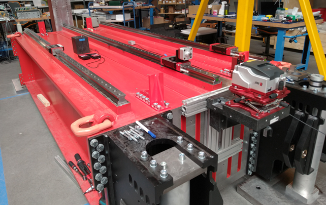
The main structure of this motion system includes a rigid steel support structures, a solid frame weighing approximately 25 tons, and a mobile lifting platform weighing about 9 tons. The vertical and horizontal motion stages employ high-precision roller guideways, for the Z axis these are mounted on granite beams. Additionally, four synchronized ball screw drives in the Z axis enable tilt correction of the platform to improve the scanning performance of the machine.
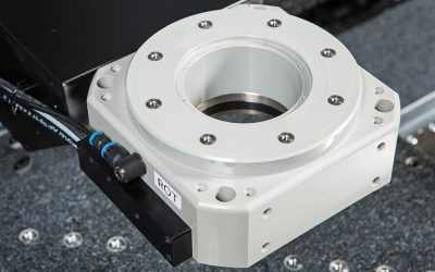
The concept involves an air bearing rotary sampling stage, which is located on the lifting platform.
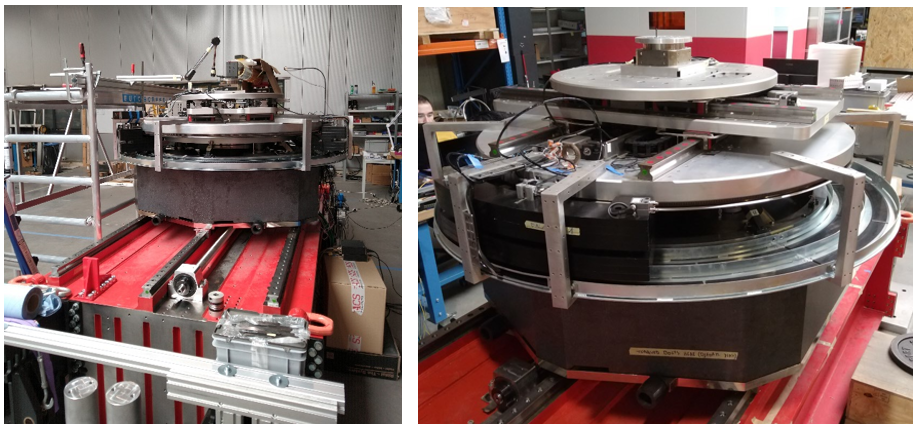
The imaging system comes with several main features that contribute to its high precision and accuracy. Firstly, it includes a rotary stage that utilizes both radial and axial air bearings, allowing for smooth and precise rotation. The error motion of this rotation stage is much better than that of rotation stages with mechanical bearings, especially the non-repeatable error or rotation is much lower than stages with mechanical bearings. Additionally, the system has an alignment stage in the X and Y directions, which utilizes high precision roller bearings and a ball screw drive. To ensure accurate imaging, the system is also equipped with a fully automated balancing system that compensates for any unbalance loads. Finally, a metrology system is included to compensate for any errors during image reconstruction from the acquired data.
An air bearing rotary stage specifically designed for this project
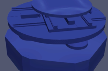
The initial concepts for the rotation stage include several options: a conventional design, form closed alternatives, and magnet preloaded concepts. The team considered various factors such as part production cost, part accuracy in relation to size, and the availability of production machines when deciding which concept to proceed with.
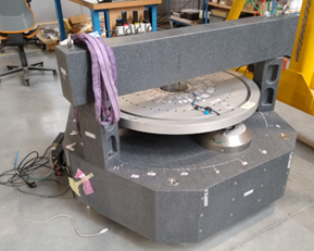
Our solution for the project involves a torque motor that is integrated into a granite block and water-cooled to minimize the thermal impact on the precision of the stage. The system uses a radial air bearing and has a conventional layout with high precision finished parts. In addition to the radial air bearing, we have also incorporated an axial air bearing with three steel pads, 300 mm diameter, placed 120° apart on a PCD of 780 mm. Each pad realises a static stiffness of 3500 N/µm, resulting in an axial stiffness of the rotation stage of 10.5 kN/µm and a tilt stiffness of 800 Nm/µrad, while the bearing still realised enough film damping to exhibit overdamped system behaviour which results in superior stability and asynchronous error motion. The high stiffness of the thrust bearing yields a robust mechanical system against the load exerted by the sample, both its weight, the introduced unbalance during rotational scanning as the eccentricity of the load onto the stage.
This design also features magnet preloading and a granite running surface for the thrust bearing. The rotation system’s top plate uses a kinematic contact configuration that features three spherical contacts between the rotary and alignment stages and includes granite flatness tuning features.
Air bearing stage in action
Accuracy values

Air bearing stage on motion platform
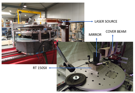
The sphere of confusion that we measured with this approach was between 1.72 and 8.18 um without any data correction. With data correction based on online measured error motion and data of a static error map (containing information about the repeatable error of the spindle), the sphere of confusion can be further reduced up to 0,85 um and potentially lower.

“We realize complete integrated motion systems for a variety of industries and clients.”
Kurt Smets – Product Development Manager
Featured products
More products
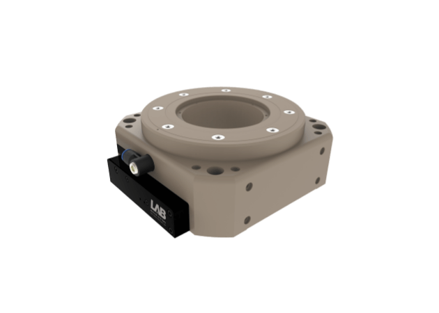
RT150AX
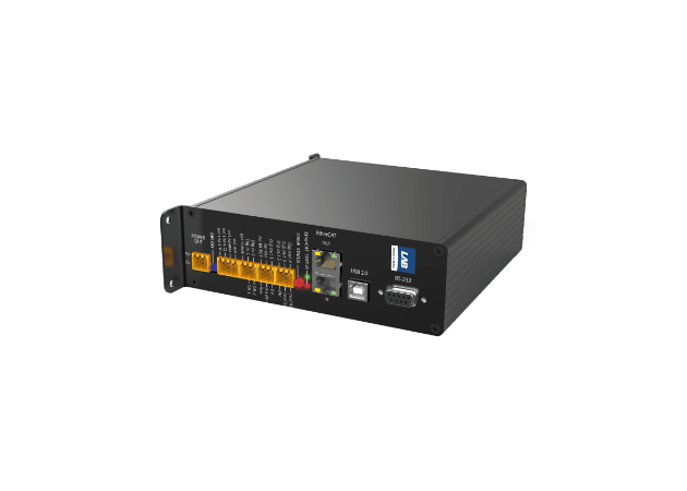
Drivebox
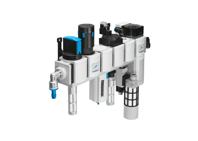
Air Filters
More stories
All cases
Optimizing Wafer Inspection with Air Bearing Stages
The implementation of LAB Motion Systems’ air bearing stages for patterned wafer inspection has delivered significant improvements in inspection efficiency and accuracy.
Case study with Siemens: Smart Virtual Sensing
This study in collaboration with Siemens shows how implementing smart virtual sensing in our air bearing systems can improve the estimates of critical machine parameters at a low cost.
4 Axis Motion System
A combination of standard products, customized products and a custom developed air bearing vertical stage. All axis can be driven and synchronized by LAB’s motion controllers or with commercially available controllers.
Optimizing Wafer Inspection with Air Bearing Stages
The implementation of LAB Motion Systems’ air bearing stages for patterned wafer inspection has delivered significant improvements in inspection efficiency and accuracy.
Case study with Siemens: Smart Virtual Sensing
This study in collaboration with Siemens shows how implementing smart virtual sensing in our air bearing systems can improve the estimates of critical machine parameters at a low cost.


